 Cameras have been around for a long time now. When cameras were first introduced, they were expensive and you needed a good amount of money to own one. However, people then came up with pinhole cameras in the late 20th century. These cameras were inexpensive and they became a common occurrence in our everyday life. Unfortunately, as is the case with any trade off, this convenience comes at a price. These pinhole cameras have significant distortion! The good thing is that these distortions are constant and they can be corrected. This is where camera calibration comes into picture. So what is this all about? How can we deal with this distortion?
Say hello to camera calibration
We can correct the camera distortion by using calibration and some remapping. Furthermore, with calibration, you can also determine the relation between the camera’s natural units (pixels) and the real world units (for example, millimeters or inches). Camera calibration is an important step towards getting a highly accurate representation of the real world in the captured images. Camera calibration can actually refer to two things: geometric calibration and color calibration. This post is about geometric calibration. We will discuss about color calibration in some other post.
What does it do?
Primarily, camera calibration is about finding the quantities internal to the camera that affect the imaging process. Here are some of the factors that will be taken care of:
- Image center: We need to find the position of the image center in the image. Wait a minute, isn’t the image center located at (width/2, height/2)? Well, not really! Unless we calibrate the camera, the image will almost always appear to be off-center.
- Focal length: This is a very important parameter. Remember how people using DSLR cameras tend to “focus” on things before capturing the image? This parameter is directly related to the “focus” of the camera and it’s very critical.
- Scaling factors: The scaling factors for row pixels and column pixels might be different. If we don’t take care of this thing, the image will look stretched (either horizontally or vertically).
- Skew factor: This refers to shearing. The image will look like a parallelogram otherwise!
- Lens distortion: This refers to the pseudo zoom effect that we see near the center of any image.
All these terms will become clear very soon as we continue our discussion here. I just wanted to list down a few things that will get affected if you don’t calibrate your camera. The image will actually look pretty awful if you don’t do camera calibration.
Pinhole Camera Model
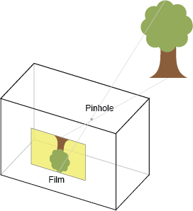 Before we jump into anything, let’s see where this all began. When we capture an image, we are basically mapping the 3D scene to a 2D image. It means that every point in the 3D world gets mapped to the 2D plane on our image. This is called the pinhole camera model. It basically describes the relationship between the coordinates of the 3D point and its projection on the 2D image. This, of course, is the ideal case where there is absolutely no distortion of any kind. Every camera is modeled based on this, and every camera aspires to simulate this as close as possible. But in the real world, we have to deal with things like geometric distortions, blurring, finite sized apertures, etc.
 The figure shown here depicts a pinhole camera model. The camera is placed at the origin O. The point P represents a point in the real world. We are trying to capture that onto a 2D plane. The “image plane” represents the 2D plane that you get after capturing the image. The image plane actually contains the image that you see after capturing a picture. So basically, we are trying to map every 3D point to a point on the image plane. In this case, the point P gets mapped to Pc. The distance between the origin O and this image plane is called the focal length of the camera. You must have seen that coming! This is the parameter you modify when you adjust the “focus” of the camera.
Intrinsic and Extrinsic Parameters
If you google these things, you will get a whole bunch of papers describing the mathematical formulation of intrinsic and extrinsic parameters. But we are here to understand what it means! So I will try to keep it simple without going into too many mathematical details. Now why did we suddenly jump from pinhole camera model to intrinsic and extrinsic parameters? Seems random, right? Well, not exactly! Let’s see what it means.
In the above figure, we want to estimate (u,v) from (X,Y,Z). Let’s say the focal length is denoted by ‘f’. If you look at the triangles formed using the origin/Pc/Z-axis and the origin/P/Z-axis, you will notice that they are similar triangles. This means that ‘u’ depends on the f, X, and Z. Similarly, ‘v’ depends on f, Y, and Z:
u = fX/Z
v = fY/Z
Next, if the origin of the 2D image coordinate system does not coincide with where the Z axis intersects the image plane, we need to translate Pc to the desired origin. Let this translation be defined by (tu, tv). So now, u and v are given by:
u = fX/Z + tu
v = fY/Z + tv
So up until now, we have something that can translate (X,Y,Z) to (u,v). Let’s denote this by a matrix M. So we can write:
Pc = MP
Since this is a camera image, we need to express it in inches. For this, we will need to know the resolution of the camera in pixels/inch. If the pixels are square the resolution will be identical in both u and v directions of the camera image coordinates. However, for a more general case, we assume rectangular pixels with resolution mu and mv pixels/inch in u and v direction respectively. Therefore, to measure Pc in pixels, its u and v coordinates should be multiplied by mu and mv respectively. So now, this new transformation matrix depends on f, X, Y, Z, tu, tv, mu, and mv. Let’s denote this by:
Pc = KP
Here, K is called the intrinsic parameter matrix for the camera.
Now if the camera does not have its center of projection at (0, 0, 0) and is oriented in an arbitrary fashion (not necessarily z-perpendicular to the image plane), then we need rotation and translation to make the camera coordinate system coincide with the configuration in that pinhole camera figure. Let the camera translation to origin of the XYZ coordinate be given by T(Tx, Ty, Tz). Let the the rotation applied to coincide the principal axis with Z axis be given by a 3×3 rotation matrix R. Then the matrix formed by first applying the translation followed by the rotation is given by the 3×4 matrix:
E = (R | RT)
This is called the extrinsic parameter matrix for the camera. Here, the symbol ‘|’ refers to just concatenating two matrices with the same number of rows. For example, if you concatenate a 3×4 matrix and 6×4 matrix, you will get a 9×4 matrix.
So, the complete camera transformation can now represented as:
K(R | RT) = (KR | KRT) = KR(I | T)
Hence Pc, the projection of P is given by:
Pc = KR(I | T)P = CP
C is a 3×4 matrix usually called the complete camera calibration matrix. So basically, camera calibration matrix is used to transform a 3D point in the real world to a 2D point on the image plane considering all the things like focal length of the camera, distortion, resolution, shifting of origin, etc. This matrix consists of parameters that are intrinsic as well as extrinsic to the camera.
—————————————————————-———————————

I’m looking for information about cameras and computer vision because I want to make a camera calibration project and this information was very usefull to me. Thanks!
There is a typo in your equation. y = fY/Z + tv . I think it is v not y.
Thanks for pointing it out. I fixed it.
Hi.. I need to find out disparity map from already stored stereo dataset in my machine.. Do I still need to do camera callibration or can I directly try SBM or SGBM?
Very nicely explained… good enough for beginners!
One typo in the subscripts – at the part where you explain m_u and m_v, you have indicated it as “mu” and “mv”
Thanks, Shibon. I have corrected the typo.
Wonderfully explained!
So, if I’m not mistaken, camera calibration needs to be carried out to map 3D points from the real world on to the 2D image plane?
Thanks!
Or, is it used to find the intrinsic and extrinsic parameters of a camera a more appropriate explanation?
I am working on Image Processing Project , in which Camera Calibration topic information was needed . This article helped me to understand very nicely
Thanks
Great explanation. Thank you so much.
I have a question about calibration. Can we use the same calibration parameters for the other scenes (in different places, with different light conditions etc) captured by the same camera? If the answer is no, how robots or autonomous cars work with the same calibration parameters for every scene?
Best wishes.